
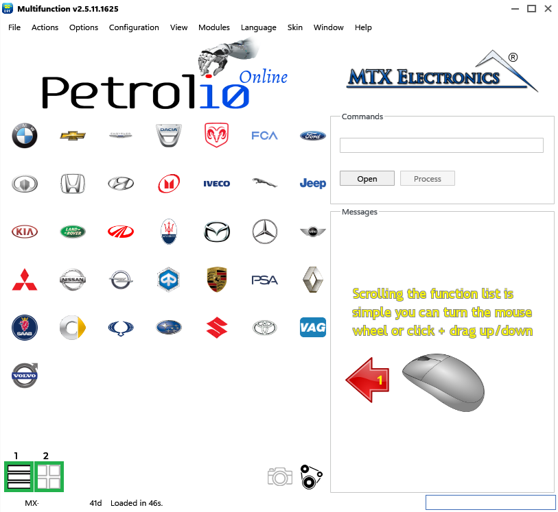
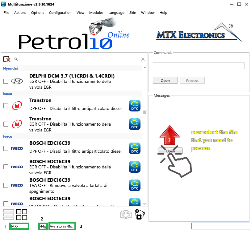
This section provides a general overview of the program, illustrating its overall structure and key features. The top menu bar provides easy access to all software features via drop-down menus.
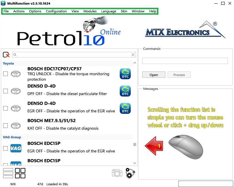
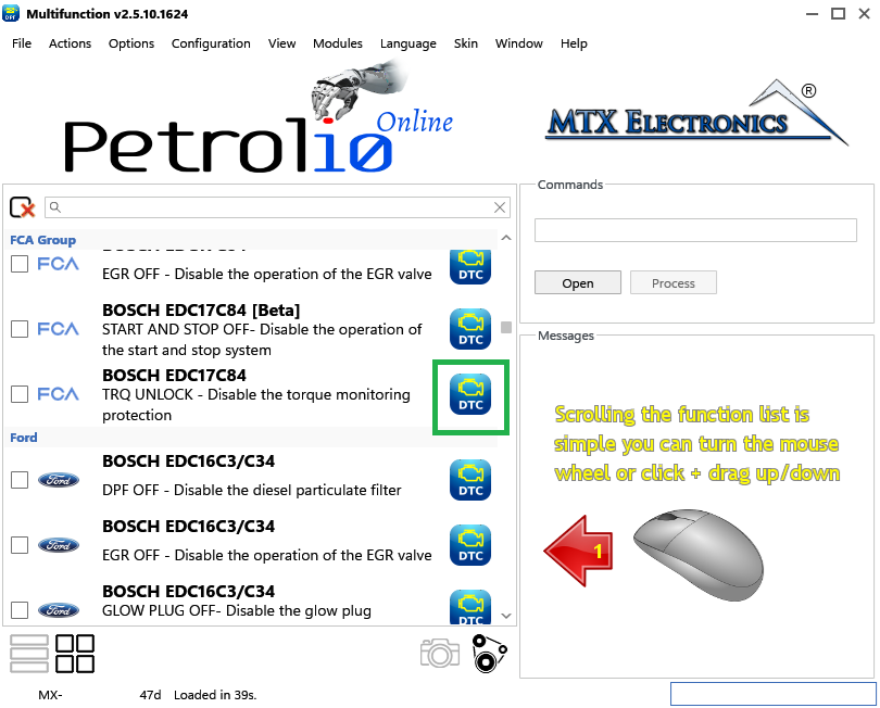
Solution List: here you can select the desired solution based on the ECU manufacturer and model. The list can be browsed using the mouse's central scroll wheel or, alternatively, by dragging the contents up or down with the left mouse button, similar to navigating a phone book on a smartphone.
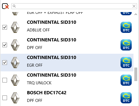
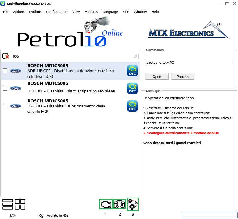
Multiple selections: you can select multiple solutions to apply to the same file by checking the checkboxes on the left. For example, in Figure 3 the ADBLUE OFF, DPF OFF and EGR OFF solutions will be applied.
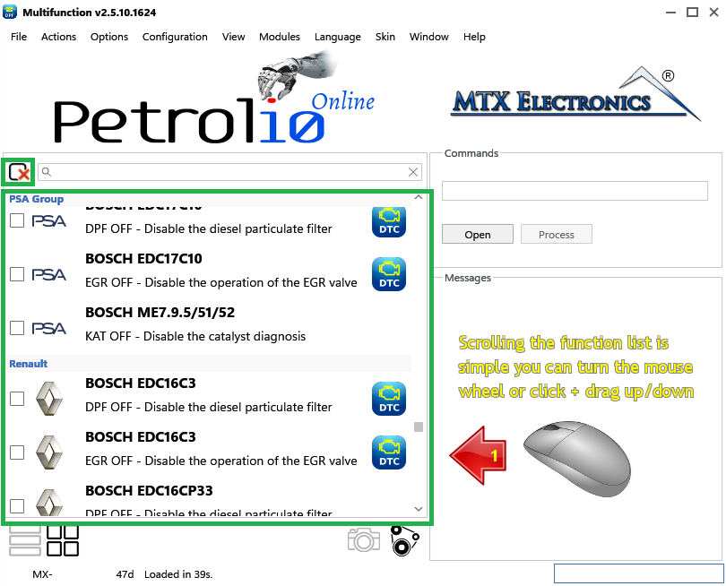
Note — To deselect all solutions and start from scratch, click the icon at the top-left of the list:
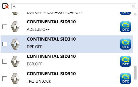
Single selections: you can also select a single solution by clicking on it, highlighting the row in blue. For example, in Figure 4 only the DPF OFF solution will be applied.
View solution type: using two buttons you can choose how to view the list of solutions — access the entire archive, or filter the solutions by vehicle manufacturer.
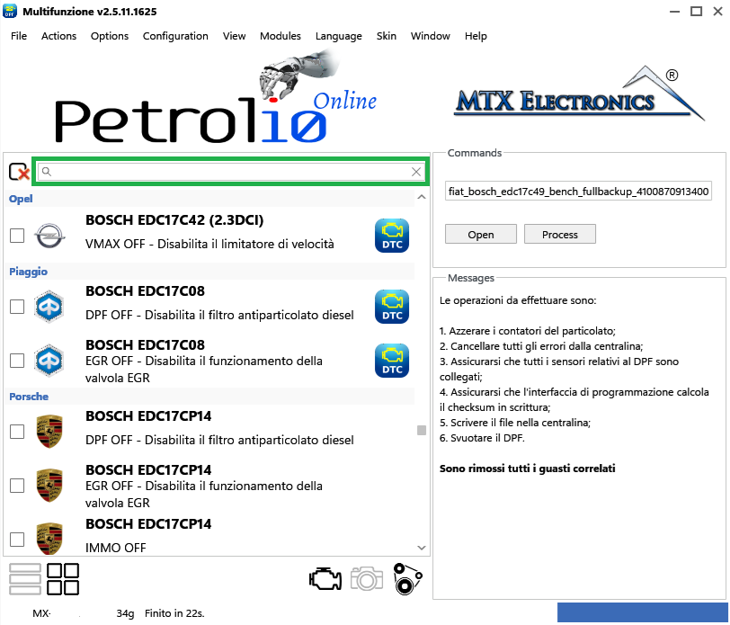
Search bar: this field filters the list of solutions by typing the name of the manufacturer, control unit, or a specific solution. Examples:
Note — Enter just the final part of the name (e.g.C39instead ofEDC16C39) for a broader, more complete search.
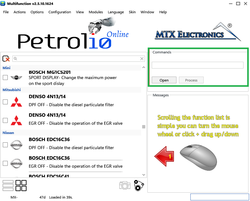
Command area: in the Commands section you can open the original file and then start processing it with the Process button.
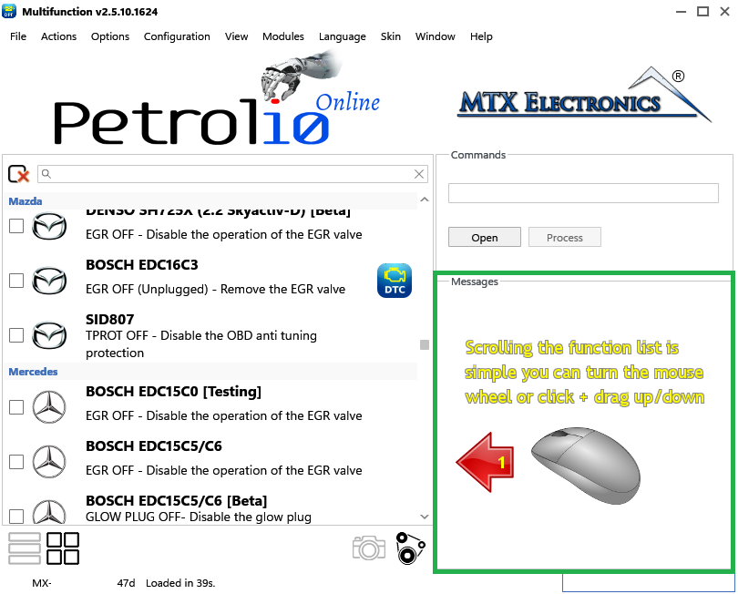
Message area: when the program starts, a message explains, in three simple steps, how to use it. After selecting a solution, a summary of the actions to perform is displayed, such as physically emptying the DPF or whether any sensors need to be disconnected.
Status bar: displays information about the licence and system messages. Box 1 shows the dongle's serial number, box 2 shows the remaining days of validity (the licence renews every 60 days), and box 3 shows the message for the operation currently in progress.
DTC icon: indicates that, for that solution, you can manually remove additional faults present in the control unit. To do so, open the top menu and select Modules › Faults Removal.
Additional functions: the icons highlighted below let you search for and delete DTCs (icon 1), view images of the control-unit allocation (icon 2), and use calculation models for various options such as volumetric efficiency or unit conversion (icon 3).
All-in-one application for tuning experts preparing vehicles for track use. Designed for professional workshops, it simplifies the deactivation of non essential components to unlock true performance.
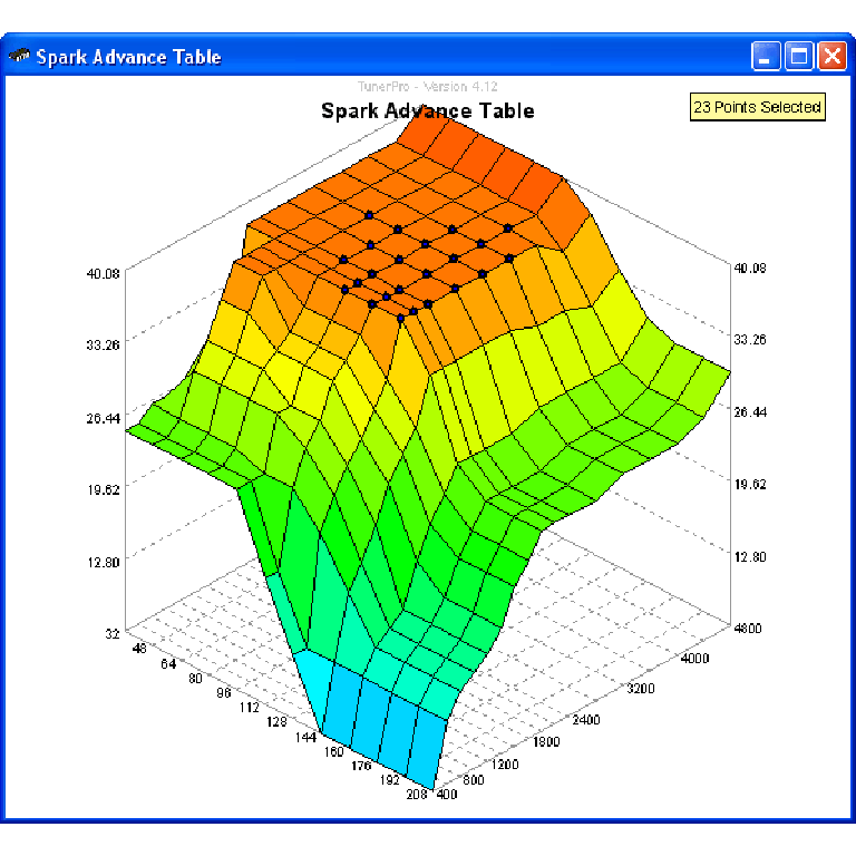
A free collection of checksum correction plugins for TunerPro that ensures safe ECU tuning. Automatically verify and update file checksums for reliable vehicle performance.
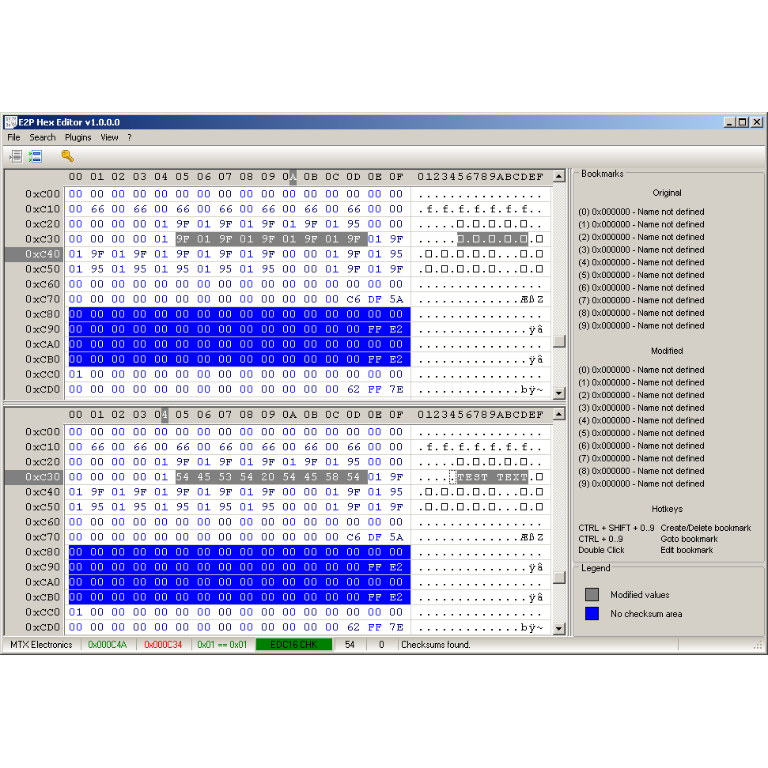
A hex editor built specifically for editing EEPROM data in automotive ECUs. With real-time checksum correction, side-by-side file comparison, and plugin support for automated tasks it's the ultimate tool for professionals.
